- 您现在的位置:买卖IC网 > Sheet目录985 > ISL29010IROZ-EVALZ (Intersil)EVALUATION BOARD FOR ISL29010
�� �
�
�ISL29010�
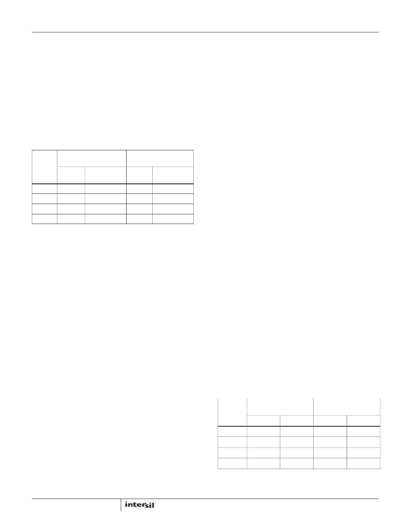
�Number� of� Clock� Cycles,� n-bit� ADC�
�The� number� of� clock� cycles� determines� “n”� in� the� n-bit� ADC;� 2� n�
�clock� cycles� is� a� n-bit� ADC.� n� is� programmable� in� the� command�
�register� in� the� width� function.� Depending� on� the� application,� a�
�good� balance� of� speed� and� resolution� has� to� be� considered�
�when� deciding� for� n.� For� fast� and� quick� measurement,� choose�
�the� smallest� n� =� 3.� For� maximum� resolution� without� regard� of�
�time,� choose� n� =� 15.� Table� 10� compares� the� trade-off� between�
�integration� time� and� resolution.� See� Equations� 10� and� 11� for� the�
�relation� between� integration� time� and� n.� See� Equation� 3� for� the�
�relation� of� n� and� resolution.�
�TABLE� 10.� RESOLUTION� AND� INTEGRATION� TIME�
�SELECTION�
�Integration� Time� or� Conversion� Time�
�Integration� time� is� the� period� during� which� the� device’s�
�analog-to-digital� ADC� converter� samples� the� photodiode�
�current� signal� for� a� lux� measurement.� Integration� time,� in�
�other� words,� is� the� time� to� complete� the� conversion� of� analog�
�photodiode� current� into� a� digital� signal� (number� of� counts).�
�Integration� time� affects� the� measurement� resolution.� For�
�better� resolution,� use� a� longer� integration� time.� For� short� and�
�fast� conversions� use� a� shorter� integration� time.�
�The� ISL29010� offers� user� flexibility� in� the� integration� time� to�
�balance� resolution,� speed� and� noise� rejection.� Integration� time�
�can� be� set� internally� or� externally� and� can� be� programmed� in�
�the� command� register� 00(hex)� Bit� 5.�
�RANGE1�
�RANGE4�
�f� OSC� =� 327kHz�
�f� OSC� =� 655kHz�
�INTEGRATION� TIME� IN� INTERNAL� TIMING� MODE�
�t� INT�
�RESOLUTION�
�t� INT�
�RESOLUTION�
�This� timing� mode� is� programmed� in� the� command� register�
�(EQ.� 9)�
�� ----------�
�t� INT� =� 2�
�n�
�15�
�11�
�7�
�3�
�(ms)�
�200�
�12.8�
�0.8�
�0.05�
�LUX/COUNT�
�0.06�
�1.0�
�15.6�
�250�
�(ms)�
�100�
�6.4�
�0.4�
�0.025�
�(LUX/COUNT)�
�2�
�62.5�
�1,000�
�16,000�
�00(hex)� Bit� 5.� Most� applications� will� be� using� this� timing�
�mode.� When� using� the� Internal� Timing� Mode,� f� OSC� and�
�n-bits� resolution� determine� the� integration� time.� t� INT� is� a�
�function� of� the� number� of� clock� cycles� and� f� OSC� .�
�m� 1�
�for� Internal� Timing� Mode� only�
�f� osc�
�R� EXT� =� 100k� Ω�
�m� =� 4,� 8,� 12,� and16.� n� is� the� number� of� bits� of� resolution.�
�External� Scaling� Resistor� R� EXT� and� f� osc�
�The� ISL29010� uses� an� external� resistor� R� EXT� to� fix� its�
�internal� oscillator� frequency,� f� OSC� .� Consequently,� R� EXT�
�determines� the� f� OSC� ,� integration� time� and� the� FSR� of� the�
�device.� f� OSC� ,� a� dual� speed� mode� oscillator,� is� inversely�
�2� m� therefore� is� the� number� of� clock� cycles.� n� can� be�
�programmed� at� the� command� register� 00(hex)� Bits� 1� and� 0.�
�Since� f� OSC� is� dual� speed� depending� on� the� Gain/Range� bit,�
�t� INT� is� dual� time.� The� integration� time� as� a� function� of� R� EXT�
�m� R� EXT�
�t� INT� 1� =� 2�
�327kHz� ×� 100k� Ω�
�proportional� to� R� EXT� .� For� user� simplicity,� the� proportionality�
�constant� is� referenced� to� fixed� constants� 100k� Ω� and�
�655kHz:�
�is� shown� in� Equation� 10:�
�� ----------------------------------------------�
�(EQ.� 10)�
�f� OSC� 1� =� ---� � ------------------� � 655� kHz�
�R� EXT�
�2�
�1� 100k� Ω�
�(EQ.� 6)�
�t� INT� 1� is� the� integration� time� when� the� device� is� configured�
�for� Internal� Timing� Mode� and� Gain/Range� is� set� to� Range1�
�f� OSC� 2� =� ------------------� � 655� kHz�
�m� R� EXT� (EQ.� 11)�
�t� INT� 2� =� 2�
�655kHz� ×� 100k� Ω�
�100k� Ω� (EQ.� 7)�
�R� EXT�
�f� OSC� 1� is� oscillator� frequency� when� Range1� or� Range2� are�
�set.� This� is� nominally� 327kHz� when� R� EXT� is� 100k� Ω� .�
�f� OSC� 2� is� the� oscillator� frequency� when� Range3� or� Range4�
�are� set.� This� is� nominally� 655kHz� when� R� EXT� is� 100k� Ω� .�
�When� the� Range/Gain� bits� are� set� to� Range1� or� Range2,�
�or� Range2.�
�� ----------------------------------------------�
�t� INT� 2� is� the� integration� time� when� the� device� is� configured�
�for� Internal� Timing� Mode� and� Gain/Range� is� set� to� Range3�
�or� Range4.�
�TABLE� 11.� INTEGRATION� TIMES� FOR� TYPICAL� R� EXT� VALUES�
�f� OSC� runs� at� half� speed� compared� to� when� Range/Gain� bits�
�RANGE1�
�RANGE3�
�f� OSC� 1� =� ---� (� f� OSC� 2� )�
�are� set� to� Range3� and� Range4.�
�1�
�2�
�(EQ.� 8)�
�R� EXT�
�(k� Ω)�
�RANGE2�
�n� =� 15-BIT� n� =� 11-BIT�
�RANGE4�
�n� =� 11-BIT� n=3�
�50�
�100�
�6.4�
�3.2�
�0.013�
�The� automatic� f� OSC� adjustment� feature� allows� significant�
�improvement� of� signal-to-noise� ratio� when� detecting� very� low�
�lux� signals.�
�100**�
�200�
�500�
�200�
�400�
�1000�
�13�
�26�
�64�
�6.5�
�13�
�32�
�0.025�
�0.050�
�0.125�
�*Integration� time� in� milliseconds�
�**Recommended� R� EXT� resistor� value�
�7�
�FN6414.1�
�November� 11,� 2011�
�发布紧急采购,3分钟左右您将得到回复。
相关PDF资料
ISL29011IROZ-EVALZ
EVAL BOARD FOR ISL29011
ISL29012IROZ-EVALZ
EVALUATION BOARD ISL29012IROZ
ISL29013IROZ-EVALZ
EVALUATION BOARD FOR ISL29013
ISL29015IROZ-EVALZ
EVALUATION BOARD FOR ISL29015
ISL29018IROZ-EVALZ
EVALUATION BOARD FOR ISL29018
ISL29020IROZ-EVALZ
EVALUATION BOARD FOR ISL29020
ISL29021IROZ-EVALZ
EVAL BOARD FOR ISL29021IROZ
ISL29023IROZ-EVALZ
EVALUATION BOARD ISL29023IROZ
相关代理商/技术参数
ISL29010IROZ-T7
功能描述:光学数位转换器 ISL29010IROZ LIGHT TO-DIGTL OUTPUT SENS RoHS:否 制造商:ams 数据总线宽度: 峰值波长:470 nm 最大工作频率: 工作电源电压: 工作电流: 最大工作温度:+ 85 C 最小工作温度:- 40 C 封装 / 箱体:Chipscale-6 封装:Reel
ISL29011IROZ-EVALZ
功能描述:EVAL BOARD FOR ISL29011 RoHS:是 类别:编程器,开发系统 >> 评估板 - 传感器 系列:* 产品培训模块:Lead (SnPb) Finish for COTS
Obsolescence Mitigation Program 标准包装:1 系列:-
ISL29011IROZ-T7
功能描述:IC PROXIMITY SENSOR AMB LT 8ODFN RoHS:是 类别:传感器,转换器 >> 多功能 系列:- 其它有关文件:Automotive Product Guide 标准包装:2,500 系列:- 传感器类型:光线和近程 输出类型:I²C?
ISL29011IROZ-T7R5484
制造商:Intersil Corporation 功能描述:ISL29011IROZ-T7 DOMINANT ASSY AND UNISEM TEST ONLY - Tape and Reel 制造商:Intersil Corporation 功能描述:IC PROXIMITY SENSOR AMB LT 8ODFN 制造商:Intersil Corporation 功能描述:ISL29011IROZ-T7 DOMINANT ASSY AND CARSEM TEST ONLY T/R
ISL29012IROZ-EVALZ
功能描述:EVALUATION BOARD ISL29012IROZ RoHS:是 类别:编程器,开发系统 >> 评估板 - 传感器 系列:- 产品培训模块:Lead (SnPb) Finish for COTS
Obsolescence Mitigation Program 标准包装:1 系列:-
ISL29012IROZ-T7
功能描述:IC SENSOR LIGHT-DGTL I2C 6-ODFN RoHS:是 类别:传感器,转换器 >> 光学 - 光电探测器 - 环境光传感器 系列:- 产品培训模块:Lead (SnPb) Finish for COTS
Obsolescence Mitigation Program 产品变化通告:Product Discontinuation 25/Jun/2012 标准包装:2,500 系列:- 带接近传感器:无 波长:- 电源电压:1.7 V ~ 2 V 电流 - 暗(标准):- 电流 - 光(典型值):- 输出类型:数字 - I²C 工作温度:-40°C ~ 85°C 安装类型:表面贴装 封装/外壳:6-UDFN 裸露焊盘 包装:带卷 (TR)
ISL29013IROZ
制造商:Intersil Corporation 功能描述:Light-To-Digital Sens,ISL29013IROZ
ISL29013IROZ-EVALZ
功能描述:EVALUATION BOARD FOR ISL29013 RoHS:是 类别:编程器,开发系统 >> 评估板 - 传感器 系列:- 产品培训模块:Lead (SnPb) Finish for COTS
Obsolescence Mitigation Program 标准包装:1 系列:-